Tampilkan postingan dengan label Mikrokontroler. Tampilkan semua postingan

LCD 2004 atau 20x4 dengan I2C Arduino

22.40 Posted by Ali Mahfud , No comments
LCD 2004 dengan I2C Arduino

Pada postingan kali ini penulis akan membuat tutorial cara menghubungkan LCD 20x4 atau LCD 2004 dengan IC I2C pada Arduino. Pada kesempatan kali ini Penulis menggunakan alat atau peralatan sebagai berikut.


I2C Version 1

LCD 20x4 atau LCD 2004
Pada IC I2C ini merupakan sebuah alat untuk memangkas pin yang dibutuhkan LCD menjadi 4 pin saja. Alat ini sangat berguna untuk pengguna yang menggunakan banyak sensor pada Arduinonya, Pin yang digunakan I2C ini adalah pin SCL dan SDA.
Untuk pengimplementasiannya I2C ini menggunakan Address untuk dihubungkan ke Arduino. Langsung saja, berikut cara-cara yang diperlukan untuk menggunakan I2C LCD 2004 kali ini.

Hal yang pertama dilakukan adalah menghubungkan rangkaian LCD 2004 I2C dengan Arduino. Konfigurasi pin I2C dan Arduino adalah sebagai berikut.

I2C          Arduino UNO                                      I2C          Arduino Mega
GND ----- GND                                                  GND ----- GND
VCC ----- 5V                                                      VCC ------ 5V
SDA ----- A4                                                       SDA ----- 20
SCL ------ A5                                                      SCL -----  21

1. Scan Address I2C
    Pertama, hal yang harus dilakukan adalah scan Address I2C yang dimiliki, walaupun biasanya Address yang digunakan adalah 0x27 namun ada juga beberapa yang menggunakan Address 0x3F. Sketch yang digunakan untuk scan adalah sebagai berikut.

Sketch:

//Pertama sertakan library Wire.h
#include <Wire.h>

void setup() {
  Serial.begin (9600);
  // Leonardo: wait for serial port to connect
  while (!Serial) 
    {
    }
  Serial.println ();
  Serial.println ("I2C scanner. Scanning ...");
  byte count = 0;
  
  Wire.begin();
  for (byte i = 8; i < 120; i++)
  {
    Wire.beginTransmission (i);
    if (Wire.endTransmission () == 0)
      {
      Serial.print ("Found address: ");
      Serial.print (i, DEC);
      Serial.print (" (0x");
      Serial.print (i, HEX);
      Serial.println (")");
      count++;
      delay (1);  // maybe unneeded?
      } // end of good response
  } // end of for loop
  Serial.println ("Done.");
  Serial.print ("Found ");
  Serial.print (count, DEC);
  Serial.println (" device(s).");
}  // end of setup
void loop() {}
Buka Serial Monitor pada Arduino IDE untuk melihat hasil Address atau alamat I2C yang terbaca.
Hasil pada serial monitor:
I2C scanner.Scanning . . .
Found address: 63 (0x3F)
Done.
Found 1 device(s).
Jika tampilan diatas muncul pada Serial Monitor, berarti proses scan address berhasil dan Address I2C yang terbaca adalah 0x3F

2. Sketch LCD 2004 atau LCD 20x4 dengan I2C
  Setelah melakukan scanning address pada IC I2C selanjutnya masuk ke Sketch Arduino untuk menampilkan karakter ke LCD 2004 atau LCD 20x4.
Hal yang dibutuhkan adalah Library untuk LCD tersebut. Library dapat didownload disini. Atau bisa di download pada menu Download.

Setelah Library sudah didownload, import atau masukkan ke Arduino IDE dengan  klik Sketch --> Include Library --> Add .ZIP Library... dan pilih library yang telah didownload tadi. Kemudian, setelah input library selanjutnya adalah memasukan atau membuat sketch pada Arduino IDE. Sketch LCD 2004 untuk arduino adalah sebagai berikut.
Sketch:
/*-----( Masukan Library yang dibutuhkan )-----*/
#include <Wire.h>  // Comes with Arduino IDE
#include <LiquidCrystal_I2C.h>

/*-----( Deklarasi Konstanta )-----*/
/*-----( Deklarasi Objek )-----*/
// Konfigurasi LCD address ke 0x3F untuk tampilan 20 karakter dan 4 baris
// Atur pin pada I2C chip untuk koneksi ke LCD:
//                    addr, en,rw,rs,d4,d5,d6,d7,bl,blpol
LiquidCrystal_I2C lcd(0x3F, 2, 1, 0, 4, 5, 6, 7, 3, POSITIVE);  // Atur LCD I2C address


/*-----( Deklarasi Variabel )-----*/
void setup()   /*----( SETUP: RUNS ONCE )----*/
{
  Serial.begin(9600);  // Mengaktifkan serial

  lcd.begin(20,4);         // inisialisasi LCD dengan 20 karakter dan 4 baris

// ------- Melakukan blink 3 kali (Opsional) -------------
  for(int i = 0; i< 3; i++)
  {
    lcd.backlight();
    delay(250);
    lcd.noBacklight();
    delay(250);
  }
  lcd.backlight(); // Diakhiri dengan backlight on  

//-------- Menulis/menampilkan karakter pada LCD ------------------
  // CATATAN: Posisi Kursor: Baris dan Karakter mulai pada 0  
  lcd.setCursor(3,0); //Huruf akan mulai pada karakter ke 4 dan baris 0 pada LCD
  lcd.print("Hello, world!");
  delay(1000);
  lcd.setCursor(2,1);
  lcd.print("From YourHand");
  delay(1000);  
  lcd.setCursor(0,2);
  lcd.print("20 by 4 Line Display");
  lcd.setCursor(0,3);
  delay(2000);   
  lcd.print("GOOD DAY");
  delay(8000);
  // Tunggu selama 8 detik untuk dapat mengetik karakter pada serial monitor 
  lcd.setCursor(0,0); //Mulai dari Karakter 0 dan baris 0
  lcd.print("Start Serial Monitor");
  lcd.setCursor(0,1);
  lcd.print("Type chars 2 display");  

}/*--(end setup )---*/


void loop()   /*----( LOOP: DIEKSEKUSI TERUS MENERUS )----*/
{
  {
    // ketika karakter datang dari serial port...
    if (Serial.available()) {
      // delay untuk menunggu pesan ditulis pada serial
      delay(100);
      // Menghapus layar
      lcd.clear();
      // Membaca semua karakter yang diketik pada serial monitor
      while (Serial.available() > 0) {
        // menampilkan setiap karakter ke lcd
        lcd.write(Serial.read());
      }
    }
  }

}/* --(end main loop )-- */

Sekian share tentang LCD 2004 atau LCD 20x4 dengan menggunakan I2C dan melakukan scan address I2C. Semoga bermanfaat.

Referensi : arduino-info.wikispaces.com
                  www.arduino.cc
               

7 Segment Display Interface Arduino

00.28 Posted by Ali Mahfud , No comments
Antarmuka 7-Segment pada Arduino


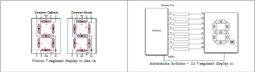
Contoh penggunaan 7 segment pada Arduino
1. One Digit Up Counter
    - Merangkai rangkaian seperti gambar di atas
Sketch :
/*
* One-digit up counter
* Displays number 0 to 9 (up counter) on one digit 7-seg display cc
*/
// bits representing segments a through g and dp for number 0-9
const byte numeral[10] = {
//abcdefg and dp
B11111100, // 0
B01100000, // 1
B11011010, // 2
B11110010, // 3
B01100110, // 4
B10110110, // 5
B00111110, // 6
B11100000, // 7
B11111110, // 8
B11100110, // 9
};
// pins for decimal point and each segment
// dp,g,f,e.d.c.b.a
const int segmentPins[8] = {9,8,7,6,5,4,3,2};
void setup()
{
for(int i=0; i < 8; i++)
{
pinMode(segmentPins[i], OUTPUT); // set all pins to output
}
}
void loop()
{
for(int i=0; i <= 10; i++)
{
showDigit(i);
delay(1000);
}
// the last value if i is 10 and this will turn the display off
delay(2000); // pause two seconds with the display off
}
// Displays a number from 0 through 9 on a 7-segment display
// any value not within the range of 0-9 turns the display off
void showDigit( int number)
{
boolean isBitSet;
for(int segment = 1; segment <= 8; segment++)
{
if( number < 0 || number > 9){
isBitSet = 0; // turn off all segments
}
else{
// isBitSet will be true if given bit is 1
isBitSet = bitRead(numeral[number], segment);
}
//isBitSet = ! isBitSet; // use this line if common anode display
digitalWrite( segmentPins[segment], isBitSet);
}
}

2. Display Input Potensiometer
Sketch:
/*
* Display input potensiometer
* Displays number 0 to 9 from a potensio on one digit 7-seg display cc
*/
// bits representing segments a through g and dp for number 0-9
const byte numeral[10] = {
// abcdefg and dp
B11111100, // 0
B01100000, // 1
B11011010, // 2
B11110010, // 3
B01100110, // 4
B10110110, // 5
B00111110, // 6
B11100000, // 7
B11111110, // 8
B11100110, // 9
};
// pins for decimal point and each segment
// dp,g,f,e.d.c.b.a
const int segmentPins[8] = {9,8,7,6,5,4,3,2};
void setup()
{
Serial.begin(9600);
for(int i=0; i < 8; i++)
{
pinMode(segmentPins[i], OUTPUT); // set all pins to output
}
}
void loop()
{
int potVal = analogRead(A0); // pin A0 for potensio
potVal=map(potVal,0,1023,0,9);
Serial.println(potVal);
showDigit(potVal);
}
// Displays a number from 0 through 9 on a 7-segment display
// any value not within the range of 0-9 turns the display off
void showDigit( int number)
{
boolean isBitSet;
for(int segment = 1; segment <= 8; segment++)
{
isBitSet = bitRead(numeral[number], segment);
//isBitSet = ! isBitSet; // use this line if common anode display
digitalWrite( segmentPins[segment], isBitSet);
}
}

3. Multiplexing two digit display 7 Segment (7 Segment 2 digit)
Sketch:
/*
* Multiplexing two-digit display sketch
* Displays the value of a potensio (0 - 99) on a multiplex two-digit display
*/
// bits representing segments a through g and dp for number 0-9
const int numeral[10] = {
//abcdefg and dp
B11111100, // 0
B01100000, // 1
B11011010, // 2
B11110010, // 3
B01100110, // 4
B10110110, // 5
B00111110, // 6
B11100000, // 7
B11111110, // 8
B11100110, // 9
};
// pins for decimal point and each segment
// dp,g,f,e.d.c.b.a
const int segmentPins[8] = {1,2,3,4,5,6,7,8};
const int nbrDigits= 2; // the number of digits in the LED display
//digit 1 2
const int digitPins[nbrDigits] = {10,11}; // 10=MSD, 11=LSD
void setup()
{
Serial.begin(9600);
for(int i=0; i < 8; i++)
pinMode(segmentPins[i], OUTPUT); // set all segs and dp pins to outp
for(int i=0; i < nbrDigits; i++)
pinMode(digitPins[i], OUTPUT);
}
void loop()
{
int potVal = analogRead(A0); // pin A0 connected to potensio
potVal = map(potVal,0,1023,0,99);
Serial.println(potVal);
showNumber(potVal);
}
void showNumber( int number)
{
if(number == 0)
showDigit(0, nbrDigits-1) ; // display 0 in the rightmost digit
else
{
// display the value corresponding to each digit
// leftmost digit is 0, rightmost is one less than the number of places
for (int digit = nbrDigits-1; digit >= 0; digit--)
{
if(number > 0)
{
showDigit(number % 10, digit) ;
number = number / 10;
}
}
}
}
// Displays given number on a 7-segment display at the given digit position
void showDigit( int number, int digit)
{
digitalWrite( digitPins[digit], HIGH );
for (int segment = 1; segment < 8; segment++)
{
boolean isBitSet = bitRead(numeral[number], segment);
// isBitSet will be true if given bit is 1
isBitSet = ! isBitSet; // use this line for common cathode display
digitalWrite(segmentPins[segment], isBitSet);
}
delay(5);
digitalWrite(digitPins[digit], LOW );
}

Antarmuka Sensor Arduino

14.45 Posted by Ali Mahfud , No comments
Antarmuka Sensor Pada Arduino

1. LDR Light Sensor

Source Code:
/*
LDR blinking rate sketch
Blink a LED with a rate based on light intensity upon an LDR
*/
const int ledPin = 2; // LED connected to digital pin 2
const int ldrPin = 0; // connect LDR to analog input 0
void setup()
{
  pinMode(ledPin, OUTPUT); // enable output on the led pin
  Serial.begin(9600);
}
void loop()
{
  int rate = analogRead(ldrPin); // read the analog input
  Serial.println(rate);
  digitalWrite(ledPin, HIGH); // set the LED on
  delay(rate); // wait duration dependent on light level
  digitalWrite(ledPin, LOW); // set the LED off
  delay(rate);
}

2. LM35 Temperature Sensor

Source Code:
/*
LM35 sketch
Prints the temperature to the Serial Monitor
*/
const int lm35Pin = 0; // LM35 connected to analog input pin 0
void setup()
{
  Serial.begin(9600);
}
void loop()
{
  int tempVal = analogRead(lm35Pin);
  Serial.print(tempVal); Serial.print(" > ");
  float millivolts = (tempVal / 1024.0) * 5000;
  float celsius = millivolts / 10; // sensor output is 10mV / Celsius
  Serial.print(celsius);
  Serial.print(" degrees Celsius, ");
  Serial.print( (celsius * 9)/ 5 + 32 ); // converts to fahrenheit
  Serial.println(" degrees Fahrenheit");
  delay(1000); // wait for one second
}

3. Dimmer

Source Code:
/*
LDR dimmer sketch
Dim a LED based on light intensity upon an LDR
*/
const int ledPin = 2; // LED connected to digital pin 2
const int ldrPin = 0; // connect LDR to analog input 0
void setup()
{
  pinMode(ledPin, OUTPUT);
  Serial.begin(9600);
}
void loop()
{
  int ldrVal = analogRead(ldrPin);
  Serial.println(ldrVal);
  delay(200);
  ldrVal = constrain(ldrVal, 20,150);
  int ledLevel = map(ldrVal,20,150, 255,0);
  analogWrite (ledPin, ledLevel);
}

4. Temperature Indicator

Source Code:
/*
LM35 sketch
Turn on a LED if temperature is greater than a threshold
*/
const int lm35Pin = 0; // sensor connected to this analog pin
const int ledPin = 2; // digital output pin for LED
const int threshold = 25; // the degree that will turn on the LED
void setup()
{
  Serial.begin(9600);
  pinMode(ledPin, OUTPUT);
}
void loop()
{
  int tempVal = analogRead(lm35Pin);
  long celsius = (tempVal * 500L) /1024; // 10 mV per degree celcius
  Serial.print(celsius);
  Serial.print(" degrees Celsius: ");
  if(celsius > threshold)
  {
    digitalWrite(ledPin, HIGH); // LED on
    Serial.println("LED is ON");
  }
  else
  {
    digitalWrite(ledPin, LOW);
    Serial.println("LED is OFF"); // LED off
  }
  delay(1000); // wait for one second
}

5. PIR Motion Detector

Source Code:
/*
PIR sketch
Turn on a LED if motion is detected
*/
const int ledPin = 9; // choose the pin for the LED
const int pirPin = 2; // choose the input pin for the PIR sensor
void setup() 
{
  pinMode(ledPin, OUTPUT); // declare LED as output
  pinMode(pirPin, INPUT); // declare PIR as input
}
void loop() 
{
  int pirVal = digitalRead(pirPin); // read input value
  if (pirVal == HIGH) // check if the input is HIGH
  {
    digitalWrite(ledPin, HIGH); // turn LED on if motion is detected
    delay(500);
    digitalWrite(ledPin, LOW); // turn LED off
  }
}

6. IR Distance Sensor

Source Code:
/*
IR-distance sketch
Display distance of object from Sharp Distance Sensor 2Y0A02
(on Serial Monitor)
*/
const int irPin = 0; // choose the pin for the IR distance sensor
float irVal, cm; //Must be of type float for pow()
void setup()
{
  Serial.begin(9600);
}
void loop()
{
  irVal = analogRead(irPin);
  //inches = 4192.936 * pow(sensorValue,-0.935) - 3.937;
  cm = 10650.08 * pow(irVal,-0.935) - 10;
  delay(100);
  Serial.print("Distance (cm) : ");
  Serial.println(cm);
}

Antarmuka Switch Arduino

13.34 Posted by Ali Mahfud , No comments
Antarmuka Switch Pada Arduino

1. Push Button

Source Code:
int ledPin = 13; // choose the pin for the LED
int switchPin = 2; // choose the input pin (for a pushbutton
int val = 0; // variable for reading the pin status
void setup() 
{
  pinMode(ledPin, OUTPUT); // declare LED as output
  pinMode(switchPin, INPUT); // declare pushbutton as input
}
void loop()
{
  val = digitalRead(switchPin); // read input value
  if (val == LOW) { // check if the input is LOW
  digitalWrite(ledPin, LOW); // turn LED OFF:
}
else 
{
  digitalWrite(ledPin, HIGH); // turn LED ON:
}
}

2. Swtich to Blink or Fade
Source Code:
/*
Blink or fade switch
Choose between Blink or Fade the LED connected to digital
pin 9, when pressing a pushbutton attached to pin 2.
The circuit:
* LED attached from pin 9 to ground
* pushbutton attached to pin 2 from +5V
* 10K resistor attached to pin 2 from ground
*/
int ledPin = 9; // choose the pin for the LED
int switchPin = 2; // choose the input pin (for a pushbutton
int val = 0; // variable for reading the pin status
int fadeval = 0;
void setup()
{
  pinMode(ledPin, OUTPUT); // declare LED as output
  pinMode(switchPin, INPUT); // declare pushbutton as input
}
void loop()
{
  val = digitalRead(switchPin); // read input value
  if (val == HIGH) { // pushed button means do blinking
    digitalWrite(ledPin, LOW); // turn LED OFF:
    delay(50);
    digitalWrite(ledPin,HIGH); //turn LED ON:
    delay(50);
  }
  else
  { // else button isn't pressed so do fading
    for(fadeval = 0 ; fadeval <= 255 ; fadeval +=5) { // fade in
    analogWrite(ledPin, fadeval); // sets the value
    delay(10);
    }
    for(fadeval = 255; fadeval >= 0 ; fadeval -=5) { // fade out
    analogWrite(ledPin, fadeval);
    }
  }
}
3. Toggle
Source Code:
// Toggle switch
/* The circuit:
* LED attached from pin 13 to ground
* pushbutton attached to pin 8 from +5V
* 10K resistor attached to pin 8 from ground
*/
int switchPin = 8;
int ledPin = 13;
boolean lastButton = LOW;
boolean ledOn = false;
void setup()
{
  pinMode(switchPin, INPUT);
  pinMode(ledPin, OUTPUT);
}
void loop()
{
  if (digitalRead(switchPin) == HIGH && lastButton == LOW)
  {
    ledOn = !ledOn;
    lastButton = HIGH;
  }
  else
  {
    lastButton = digitalRead(switchPin);
  }
  digitalWrite(ledPin, ledOn);
}

4. PWM Switch

Source Code:
// PWM Switch (with debounce)
int switchPin = 8;
int ledPin = 3;
boolean lastButton = LOW;
boolean currentButton = LOW;
int ledLevel = 0;
void setup()
{
  pinMode(switchPin, INPUT);
  pinMode(ledPin, OUTPUT);
}
boolean debounce(boolean last)
{
  boolean current = digitalRead(switchPin);
  if (last != current)
{
  delay(5);
  current = digitalRead(switchPin);
}
return current;
}
void loop()
{
  currentButton = debounce(lastButton);
  if (lastButton == LOW && currentButton == HIGH)
  {
    ledLevel = ledLevel + 51;
  }
  lastButton = currentButton;
  if (ledLevel > 255) ledLevel = 0;
  analogWrite(ledPin, ledLevel);
}

5. Interactive Traffic Lights

Source Code:
// Interactive Traffic Lights
int carRed = 12; // assign the car lights
int carYellow = 11;
int carGreen = 10;
int pedRed = 9; // assign the pedestrian lights
int pedGreen = 8;
int button = 2; // button pin
int crossTime = 5000; // time allowed to cross
unsigned long changeTime; // time since button pressed
void setup() 
{
  pinMode(carRed, OUTPUT);
  pinMode(carYellow, OUTPUT);
  pinMode(carGreen, OUTPUT);
  pinMode(pedRed, OUTPUT);
  pinMode(pedGreen, OUTPUT);
  pinMode(button, INPUT); // button on pin 2
  digitalWrite(carGreen, HIGH); // turn on the green light
  digitalWrite(pedRed, HIGH);
}
void loop() 
{
  int state = digitalRead(button);
  // check if button is pressed and it is over 5s since last button press
  if (state == HIGH && (millis() - changeTime) > 5000) {
    changeLights(); // Call the function to change the lights
  }
}
void changeLights()
{
  digitalWrite(carGreen, LOW); // green off
  digitalWrite(carYellow, HIGH); // yellow on
  delay(2000); // wait 2 seconds
  digitalWrite(carYellow, LOW); // yellow off
  digitalWrite(carRed, HIGH); // red on
  delay(1000); // wait 1 second till its safe
  digitalWrite(pedRed, LOW); // ped red off
  digitalWrite(pedGreen, HIGH); // ped green on
  delay(crossTime); // wait for preset time period
                    // flash the ped green
  for (int x=0; x<10; x++)
  {
    digitalWrite(pedGreen, HIGH);
    delay(250);
    digitalWrite(pedGreen, LOW);
    delay(250);
  }
  // turn ped red on
  digitalWrite(pedRed, HIGH);
  delay(500);
  digitalWrite(carYellow, HIGH); // yellow on
  digitalWrite(carRed, LOW); // red off
  delay(1000);
  digitalWrite(carGreen, HIGH);
  digitalWrite(carYellow, LOW); // yellow off
  changeTime = millis(); // record the time since last change of
                        // lights
}

Project LED Arduino UNO

16.27 Posted by Ali Mahfud , No comments
Praktikum Arduino UNO dengan LED

1. Blink
/*
  Blink
  Turns on an LED on for one second, then off for one second, repeatedly.
 
  This example code is in the public domain.
 */
 
// Pin 13 has an LED connected on most Arduino boards.
// give it a name:
int led = 13;

// the setup routine runs once when you press reset:
void setup() {                
  // initialize the digital pin as an output.
  pinMode(led, OUTPUT);     
}

// the loop routine runs over and over again forever:
void loop() {
  digitalWrite(led, HIGH);   // turn the LED on (HIGH is the voltage level)
  delay(1000);               // wait for a second
  digitalWrite(led, LOW);    // turn the LED off by making the voltage LOW
  delay(1000);               // wait for a second
}

2. Fade


// Fading LED
int value = 0; // variable to keep the actual value
int ledpin = 9; // light connected to digital pin 9
void setup()
{
// nothing for setup
}
void loop()
{
  for(value = 0 ; value <= 255; value+=5) // fade in (from min to max)
  {
  analogWrite(ledpin, value); // sets the value (range from 0 to 255)
  delay(30); // waits for 30 milli seconds to see the dimming effect
}
for(value = 255; value >=0; value-=5) // fade out (from max to min)
{
  analogWrite(ledpin, value);
  delay(30);
  }
}

3. Candle Light

/*
* CandleLight
*
* Use random numbers to emulate a flickering candle with a
* PWM'd LED
*
*/
int ledPin = 6; // select the pin for the LED
int val = 0; // variable that holds the current LED brightness
int delayval = 0; // variable that holds the current delay time
void setup() 
{
  randomSeed(0); // initialize the random number generator
  pinMode(ledPin, OUTPUT); // declare the ledPin as an OUTPUT
}

void loop() 
{
  val = random(100,255); // pick a random number between 100 - 255
  analogWrite(ledPin, val); // set the LED brightness
  delayval = random(50,150); // pick a random num between 50, 150
  delay(delayval); // delay that many milliseconds
}

4. Moodlight

/*
* RGB_LEDs sketch
* RGB LEDs driven from analog output ports
*/
const int redPin = 6; // choose the pin for each of the LEDs
const int greenPin = 5;
const int bluePin = 3;
const boolean invert = false; // set true if common anode, false if
// common cathode
int color = 0; // a value from 0 to 255 representing the hue
int R, G, B; // the Red Green and Blue color components

void setup()
{
// pins driven by analogWrite do not need to be declared as outputs
}

void loop()
{
  int brightness = 255; // 255 is maximum brightness
  hueToRGB( color, brightness); // function to convert hue to RGB
  // write the RGB values to the pins
  analogWrite(redPin, R);
  analogWrite(greenPin, G);
  analogWrite(bluePin, B );
  color++; // increment the color
  if(color > 255)
  color = 0;
  delay(10);
}

// function to convert a color to its Red, Green, and Blue components.
void hueToRGB( int hue, int brightness)
{
  unsigned int scaledHue = (hue * 6);
  unsigned int segment = scaledHue / 256; // segment 0 to 5 around
  // the color wheel
  unsigned int segmentOffset = scaledHue - (segment * 256); // position
  // within the seg
  unsigned int complement = 0;
  unsigned int prev = (brightness * ( 255 - segmentOffset)) / 256;
  unsigned int next = (brightness * segmentOffset) / 256;
  if(invert)
  {
    brightness = 255-brightness;
    complement = 255;
    prev = 255-prev;
    next = 255-next;
  }
  
  switch(segment ) {
        case 0: // red
    R = brightness;
    G = next;
    B = complement;
    break;
    
    case 1: // yellow
    R = prev;
    G = brightness;
    B = complement;
    break;
    
    case 2: // green
    R = complement;
    G = brightness;
    B = next;
    break;
    
    case 3: // cyan
    R = complement;
    G = prev;
    B = brightness;
    break;
    
    case 4: // blue
    R = next;
    G = complement;
    B = brightness;
    break;
    
    case 5: // magenta
    default:
    R = brightness;
    G = complement;
    B = prev;
    break;
  }
}


Sumber : Catatan Praktikum

Memulai Arduino UNO

14.06 Posted by Ali Mahfud , No comments


Getting Started dengan Arduino UNO pada Windows

Kali ini saya ingin share cara menggunakan Arduino Uno, bagi yang ingin berkecimpung di dunia Mikrokontroler dapat membaca tutorial dibawah..

1.      Menggunakan Arduino dan USB cable
Pada tutorial ini, kami mengasumsikan anda menggunakan Arduino Uno.

Anda juga membutuhkan USB kabel (A to B): atau dengan kata lain kabel USB printer. Kalau sudah dicolok dengan kabel USB printer ke PC/Laptop, tidak usah lagi menggunakan adapter power.

2.      Download Arduino IDE
Arduino IDE merupakan software dimana untuk mengupload sketch (istilah coding pada Arduino) ke Arduino UNO.

Arduino IDE 1.0.5 dapat di download disini
Kemudian install Arduino IDE tersebut.

3.      Install Driver pada PC/Laptop supaya Arduino Uno terbaca.
·        Colok Arduino Uno dengan USB kabel dan hubungkan ke PC, tunggu hingga Windows memulai proses installasi driver. Setelah beberapa saat akat tampil pesan gagal.
·        Masuk ke Control Panel > Cari Device Manager.
·        Lihat port (COM&LPT) yang ada pada device manager. Cari yang namanya “Arduino UNO (COMxx)”
·        Klik kanan pada port tersebut pilih “Update Driver Software”.
·        Selanjutnya, pilih “Browse my computer for Driver software”.
·        Cari Folder Arduino IDE 1.0.5 tadi yang sudah terinstall biasanya ada di C:/Program Files/Arduino. Pilih yang folder driver. Telihat seperti Gambar dibawah.

4.      Menjalankan Arduino IDE 1.0.5
Dengan cara mendouble click Arduino IDE yang sudah terinstall.

5.      Buka file example Blink
Open contoh LED blink dengan cara File > Examples > 1.Basics > Blink


6.   Memilih Board Arduino yang dipakai dengan cara Tools > Board pilih tipe Arduino yang dipakai.
7.   Memilih serial port dari Tools > Serial Port menu, pastikan port serial Arduino terdeteksi dan tercentang.
8.   Compile sketch sebelum di upload ke Arduino. Apabila sudah “Done” maka lakukan Upload sketch dengan menekan tombol anak panah ke kanan.

Jika sketch sudah terupload, maka led yang ada di dekat pin 13 akan berkedip.

Selamat Mencoba….
Sumber : arduino reference from Arduino IDE 1.0.5